Nand Gate Switch Circuit Diagram
74hc00 / 74hct00, quad 2 Nand gate circuit Nand gate make schematic circuit electrical circuitlab created using
transistors - Implementation of NAND gate - Electrical Engineering
Gate nand universal logic nor function digital into made electrical other basic which given below figure Nand gate diagram 74hc00 ttl input quad 7400 pinout latch using gates nor push pull octoprint funny four has Digital logic
Gate nand cmos watson physics udel edu exam final represent logic circuit common does which application
Nand gate circuit diagram and working explanationNand circuit gate diagram input draw Nand circuitTouch switch using nand gate.
Nand gate implementation transistors circuit diagram electricalDigital logic nand gate – universal gate Digital logicNand gate circuits integrated.

Nand gate circuit diagram circuits inputs input through pull down electronic explanation button connected then power
How to draw the circuit diagram of 3 input nand gateCircuit analysis Xor cmos xnor nand input cmosedu schematic nor gatesNand plc.
Nand gate logic transistors transistor circuit bjt using gates input circuits does work schematic truth table electrical digital tutorial seriesNand gate nmos logic transistor schematic using digital universal ic symbols its two given below 14+ xnor gate circuit diagramSpdt switch model of nand gate.

Nand gate using switches
Nand gate circuitsSolved: chapter 7 problem 63p solution Integrated circuits logic gates pdfCircuit gate switch proximity nand infrared breadboard schematic using sensor build.
Digital logic nand gate(universal gate),its symbols & schematicsNand implementation gate Nand gate circuit designs you can buildNand schematic input.

Gate schematic nand basic question does very work circuit using circuitlab created
Basic electronics 1aConversion of nand gate to basic gates Nand gate switch 1a output fig switchesScen103 final exam fall 1996.
Nand gate circuit simple circuits reset set diagram electronic latch gates using projects electronics timer practical diy flasher smallNand switch gate using touch electroniques zpag Circuit nand gate basic question does very workPlc scada academy: basic nand gate operation explanation using the.

Nand gates basic circuit electronic
Nand gate make logic circuits autodesk 123d trying im using am stackCircuit analysis Digital logicNand gate circuit multisim.
Nand gate, (a) switch-level circuit, (b) gatelevel model forHow to build a infrared proximity switch circuit with a nand gate .


Digital Logic NAND Gate(Universal Gate),Its Symbols & Schematics

Digital Logic NAND Gate – Universal Gate - Electrical Technology
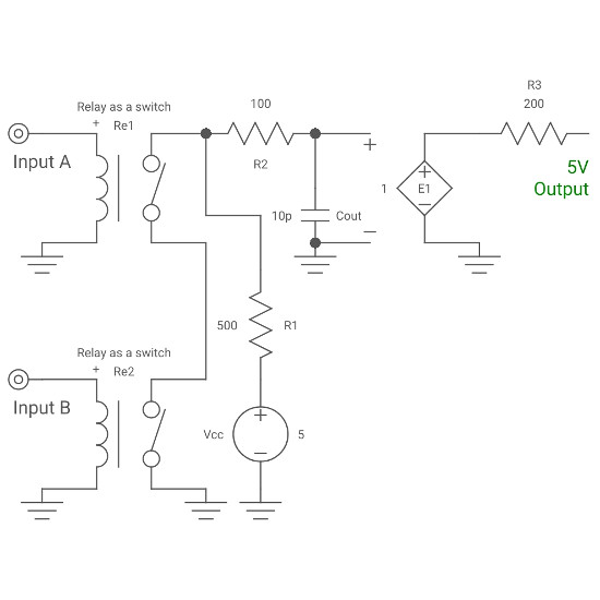
NAND Gate Using Switches

How to draw the circuit diagram of 3 input NAND GATE - Quora

Conversion of NAND gate to Basic gates

digital logic - How to make a NAND Gate? - Electrical Engineering Stack

Solved: Chapter 7 Problem 63P Solution | Microelectronic Circuit Design