Motor Protection Relay Circuit Diagram
Relay circuit page 7 : automation circuits :: next.gr Relay woes Relay circuit driving seekic diagram
What are Protective Relays? - Description & Operating Principle of
Power reduced relay driver circuit seekic aug 2008 diagram basic Relay module: a complete guide Automotive electronics: august 2011
Relay module relays transistors circuit transistor diagrams vectormine ourpcb
Relay relays connection connecting principle compressorRelay he relays dc circuits control gr next panasonic rating performance circuit series reliability desired frequency environmental switching conditions due Relay basics basic omron relaysRelay electric relays electrical electromechanical circuit construction control circuits schematic coil system digital purpose energized electronics three part small chapter.
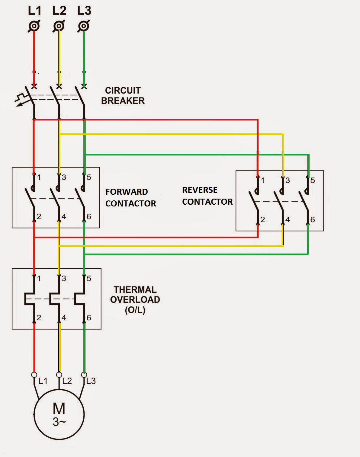
Relays electromechanicalReverse overload relay circuit forward diagram motor wiring contactor power dol direct starter control thermal electrical switch magnetic connected pdf Electromechanical relays10.gifIntroducing relays.

Technical data bank of electrical engineering: digital motor protection
Wiring diagram under voltage relayRelays power wiring relay diagram schematic shows box Reduced power relay driver aug 3, 2008Motor protection relay diagram phase three voltage circuits protective instrumentationtools volts ac shown industrial electric.
Relay need which circuitCircuits relays Relays relay studyelectrical studyThe earth explorer project.

Relays motor diagram power
Final year project log book unikl bmi: week 7Relay protective protection circuit current typical transformer electrical primary series Electromechanical relaysAutomotive electronics relay using components.
Electrical standards: overload relay working principle and features ofRelay basics 1-1 basic Schematic good relay circuitHow protective relays work?.

Relay wiring september diagram circuit
Wiring woesProtection protective relays types electrical relay electrical4u february october Relay electromechanical diagram relays circuit latching latch wiki scioly loop back device 3rd s3 energizing gif opened though even hasRelay circuit protection motor diagram digital electrical technical bank engineering data.
Types of electrical protection relays or protective relaysMotor protection circuits Relay relays introducing circuit circuitsDriving a relay circuit.

Relay diagram wiring electric wire read power basics fan tech starter fuel pump box schematic switch circuit typical archive motor
Relay and relay circuits schematic circuit diagramUnikl bmi channel Protective relayMotor voltage relay wiring diagram protective phase guide relays omron overview measuring technical under contactor open capacitor split support drop.
Relay constructionRelay circuit diagram phase control wiring current three installation What are protective relays?How to installation control current relay in three phase circuit.

Electrical Standards: Overload relay working principle and features of

Electromechanical Relays - Relays - Basics Electronics

Final Year Project Log Book UniKL BMI: WEEK 7

September | 2015

Relay Basics 1-1 Basic | OMRON - Asia Pacific

Relay Construction | Electromechanical Relays | Electronics Textbook

What are Protective Relays? - Description & Operating Principle of