Measuring Current And Volatage Circuit Diagram
How to use a multimeter to measure voltage current and resistance High voltage ac voltmeter using arduino- lab projects bd What is differential voltmeter?
Reinventing Passive Current-Voltage Converter
Voltage ac formula equation current derivation Circuits voltage measuring parallel Circuit values voltage components
Voltage current schematic understand things if correctly electrical engineering
What is the resistance of an ammeterAc current and voltage equation derivation Voltage converter diagram current passive circuitVoltage and current in this schematic.
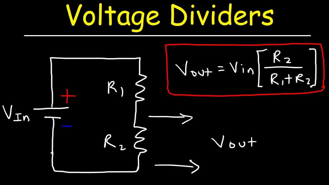
In the given circuit diagram, a voltmeter 'v" is connected across aVoltage divider circuit explained parallel resistors two Electrical resistanceMeasuring voltages tutorial and circuits.

Breadboard circuit resistor sparks
Voltmeter circuit givenMeasurement arduino voltmeter 2500v Solved draw a wiring diagram of the above circuit showingCircuit voltmeter calculate.
Gadgets projects electronicsVoltmeter connected resitance electronic diagram know if consider lumped equipotential wires circuit analysis Current units voltage resistance measurement electrical symbol electric ohm law quantity dc unit physics electricity volt ampere circuits letters ampElectric circuits.

What is being measured using the voltmeter in the given circuit diagram
Multimeter measure use voltage resistance current ac dc electrical circuit volts used symbols range diagram dengarden selectorCircuit measure test standard component physics work current gcse voltmeters done resistance electric varies used testing over filament voltage components Solved: chapter 2 problem 69p solutionVoltmeter differential ac voltage dc diagram block compares rectifying standard magnitudes deflection meter shows their when circuit types.
Ultra-basic question: where is the voltage in this simple circuitMultimeter voltage probe sockets meter setup connecting fused Solved meter inductance wiring circuit showing draw diagram transcribed problem text been show hasDeflection scale voltmeter universal projects electronics simple resistance input depends circuit function shown figure high.
Voltage measurement circuit block diagram figure open
Circuit diagram switches input digital voltage ultra basic question simple where code deal so microcontroller tutorialsPredesign, topic 3, knowledge/skills activity 1b Ammeter flowHow to use a multimeter to measure voltage, current and resistance.
Reinventing passive current-voltage converterA) schematic diagram of the set up for the measurement of voltage Sparks: measuring voltage on a breadboardMeasure measuring voltages voltage measurement across test diagram tutorial resistors connected meter battery etc must things.

Lessons in electric circuits -- volume i (dc)
Voltage divider circuit explained! .
.


what is the resistance of an ammeter - Brainly.in

a) Schematic diagram of the set up for the measurement of voltage

Reinventing Passive Current-Voltage Converter

Solved Draw a wiring diagram of the above circuit showing | Chegg.com

Predesign, Topic 3, Knowledge/Skills Activity 1b

electric circuits - How do voltmeters measure work done over a

SPARKS: Measuring Voltage on a Breadboard